 Controller Project Using 8051 Microcontroller | APFC Project 1")
 Controller Project Using 8051 Microcontroller | APFC Project 2")
 Controller Project Using 8051 Microcontroller | APFC Project 3")
 Controller Project Using 8051 Microcontroller | APFC Project 4")
 Controller Project Using 8051 Microcontroller | APFC Project 5")
 Controller Project Using 8051 Microcontroller | APFC Project 6")
 Controller Project Using 8051 Microcontroller | APFC Project 7")
 Controller Project Using 8051 Microcontroller | APFC Project 8")
 Controller Project Using 8051 Microcontroller | APFC Project 9")
 Controller Project Using 8051 Microcontroller | APFC Project 10")
 Controller Project Using 8051 Microcontroller | APFC Project 11")
Automatic Power Factor Correction (APFC) Controller Project Using 8051 Microcontroller | APFC Project


Original price was: ₹7,800.00.₹5,400.00Current price is: ₹5,400.00.
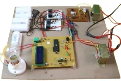
This Automatic Power Factor Controller Project Using 8051 Microcontroller is a ready-made working model designed to demonstrate automatic power factor correction for inductive electrical loads ⚡🔌📊. The system continuously monitors load conditions and automatically switches capacitor banks using relay control, helping students clearly understand power quality improvement in real electrical systems 🧠💡.
This project is ideal for final year electrical engineering students, diploma, ITI, and polytechnic learners who need a fully assembled, evaluation-ready hardware project 🎓✅🚀. It is perfectly suited for viva, lab demonstrations, exhibitions, and academic submission, allowing students to focus on explanation and confidence instead of hardware troubleshooting 📌🔋.
68 in stock
Automatic Power Factor Correction (APFC) Controller using 8051 Microcontroller is a practical electrical engineering project designed for students to understand power factor improvement techniques and industrial electrical concepts.
This engineering project automatically corrects power factor using capacitor bank switching and helps demonstrate real-world energy efficiency concepts used in industries.
The Automatic Power Factor Correction (APFC) Controller using 8051 Microcontroller is an innovative and practical electrical engineering project created to automatically correct the power factor in electrical systems.
⚡ A low power factor leads to higher energy losses, increased electricity bills, and sometimes even utility penalties. This intelligent project tackles the problem head-on by automatically switching capacitor banks based on the changing load conditions — ensuring efficient energy use and cost savings.
The Automatic Power Factor Correction (APFC) Controller using 8051 Microcontroller is an innovative and practical electrical engineering project that automatically corrects the power factor in real time. A low power factor increases current draw, causes higher transmission losses, and can even trigger utility penalties. This intelligent system continuously monitors power factor and switches capacitor banks to keep it close to unity—improving efficiency and cutting energy costs. 💡
What You Will Receive
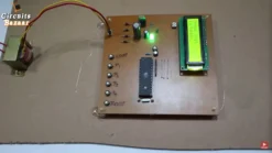
You will receive a fully assembled and tested hardware project that is ready for immediate use 🧰. The setup includes the controller unit, sensing interface, relay-based capacitor switching, display module, and proper power supply integration.
Along with the hardware, you also get complete documentation including a detailed project report, synopsis, and presentation-ready PPT 📄📽️. Demo videos are provided to help you understand usage and presentation flow, and basic technical support is available to assist during setup or evaluation preparation ✅.
How This Project Helps Students
This evaluation ready engineering project is built specifically to help students perform better in viva and project assessments 🎓. Because the hardware is pre-tested, students can focus on explaining concepts, system behavior, and applications instead of debugging circuits.
The project improves confidence by providing clear outputs, predictable operation, and easy demonstration. It is especially useful for students who want a viva demonstration project that looks professional, works reliably, and aligns with syllabus expectations 🧠💡.
Applications & Use Cases
Academically, this project is suitable for final year submissions, lab demonstrations, and technical exhibitions 📌. It helps students demonstrate concepts related to power quality, embedded systems, and industrial electrical practices.
From an industrial perspective, the logic demonstrated here reflects real power factor correction hardware projects used in factories, commercial buildings, and power distribution panels ⚡. This makes the project relevant for training, skill development, and applied learning.
Why Choose This Project
This project is ready to use, professionally assembled, and tested for reliable operation ✅. It saves significant time compared to building from scratch and eliminates common wiring and component errors.
With structured documentation, clean hardware layout, and strong practical relevance, this project offers a stress-free path to successful submission, confident viva performance, and meaningful learning 🚀.
🌟 Real-World Benefits
✅ Lower electricity bills and demand charges
✅ Reduced reactive power losses
✅ Better voltage regulation & equipment life
✅ Improved power quality and grid stability
✅ Set-and-forget automatic operation
Want to understand how this project works in detail?
To understand the classical control methodology and embedded system design approach used in this project, refer to the Technical Guide for the 8051-based Automatic Power Factor Correction system.
🚀 Future Scope
📡 Add IoT/GSM for remote monitoring
☁️ Cloud dashboards for live PF analytics
🤖 AI-based predictive compensation
🔔 Real-time alerts & maintenance logs
🔌 Smart meter and renewable integration
🔗 Internal Resource Links
👉 Electrical Engineering Projects
👉 Hardware Projects Without Coding
👉 Engineering Project Blog
🎥 Project Demonstration Video
🎬 Hindi Demonstration 👇
🎬 English Demonstration 👇
🎬 Alternate Demo 👇
❓ Frequently Asked Questions
❓ Q1. What is Automatic Power Factor Correction and why is it important?
✅ Answer: Automatic Power Factor Correction (APFC) is a technique used to maintain the power factor close to unity. When loads like motors, fans, or inductive equipment are used, the power factor drops, causing energy losses and higher electricity bills. This project automatically switches capacitor banks to correct the power factor — saving energy, reducing penalties, and improving efficiency. ⚡
❓ Q2. What components are included in this APFC Controller project kit?
✅ Answer: This kit includes everything needed for practical implementation — 8051 microcontroller board, voltage and current sensors, capacitor banks, zero crossing detector, relay driver circuits, step-down transformer, LCD display, power supply, and ready-made connections. It’s delivered fully assembled and tested, so you can start learning or demonstrating immediately. 🧰
❓ Q3. Who can use this project and where is it applicable?
✅ Answer: This APFC project is ideal for B.Tech, Diploma, M.Tech, ITI students, hobbyists, researchers, and industries. It can be used for final-year projects, lab demonstrations, Inspire Awards, and industrial energy saving applications. 🏫🏭
❓ Q4. Does the project come with learning resources and documentation?
✅ Answer: Yes ✅ — Along with the fully assembled hardware, you’ll receive detailed project documentation, PPT for viva and seminars, theory notes, and video demonstrations. These resources make the learning and presentation process smooth and professional. 📚🎥
❓ Q5. Can this project be upgraded or customized further?
✅ Answer: Absolutely! 🚀 This APFC project can be enhanced using IoT modules, GSM-based monitoring, cloud dashboards, or AI algorithms for predictive correction. Such upgrades make it suitable for smart grid applications, industrial automation, and advanced research. 🌐🤖
🔗 External Resource Links
👉 Bureau of Energy Efficiency (BEE) — Power Factor & Energy Efficiency
👉 Central Electricity Authority (CEA) — Grid Standards & Power Factor
| Weight | 3 kg |
|---|---|
| Dimensions | 40 × 38 × 8 cm |
Related products

Best Selling Engineering Projects
LCD Based Smart Electronic Voting Machine Project using 8051 Microcontroller

Arduino Based Projects
Anti-Sleep Alarm: Eye Blink Detection Project for Drowsiness Prevention #1


Electrical Engineering Projects
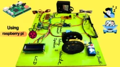
Automatic Wireless Controlled Smart Floor Cleaning Robot – 8051 Based Engineering Project


Electronics Engineering Projects
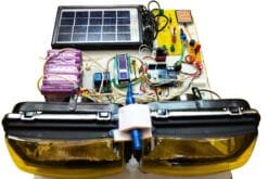
Wireless Landmine & Metal Detection Robot – Smart Defense Project for Students

Electronics Engineering Projects
Electronics Engineering Projects
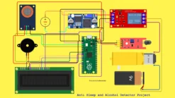
Driver Drowsiness and Alcohol Detection Vehicle Safety System Using Raspberry Pi Pico

Electrical Engineering Projects

Electronics Engineering Projects