Electrical Engineering Project Blogs
Underground Cable Fault Distance Locator Using Arduino, 16*2 LCD and Relays
Introduction
In today’s rapidly evolving world, underground cables play a crucial role in power distribution systems, telecommunications, and other essential services. However, locating faults in these cables is a significant challenge. To address this, we introduce the “Underground Cable Fault Distance Locator Project” powered by Arduino, an innovative solution for accurately detecting and displaying the fault location in underground cables.
This project is an excellent choice for engineering students, electronics enthusiasts, and professionals looking to implement a practical and impactful idea. Below, we’ll explore its features, components, working principle, and more.
🛒 Buy Fully Assembled Project (H2)
If you are a student who wants to concentrate on understanding the working principle, fault analysis logic, relay operation, and viva preparation rather than assembling and debugging hardware, you can directly use the fully assembled Underground Cable Fault Distance Locator project available on Circuits Bazaar.
The Importance of Underground Cable Fault Detection
Underground cables play a critical role in modern infrastructure, carrying power, data, and communication signals across cities and regions. However, these cables are susceptible to wear and tear, environmental factors, and accidental damage, which can lead to faults. Detecting and repairing these faults quickly is essential to ensure uninterrupted services and prevent costly downtime.
Why is this project important?
Underground cables are prone to faults caused by weather, excavation, or aging. Unlike overhead lines, detecting these faults is difficult without sophisticated systems. This Arduino-based underground cable fault detector simplifies the process by identifying the fault’s location and distance from the source.
By employing Arduino UNO, an LCD display, and relays, this project provides an easy-to-understand output that aids in quick repair and maintenance, reducing downtime and costs.
Target Keywords
- Underground cable fault detection project
- Arduino-based fault detector
- Underground cable distance locator
- Innovative engineering project
- LCD and relay-based cable fault system
Video Demonstration:
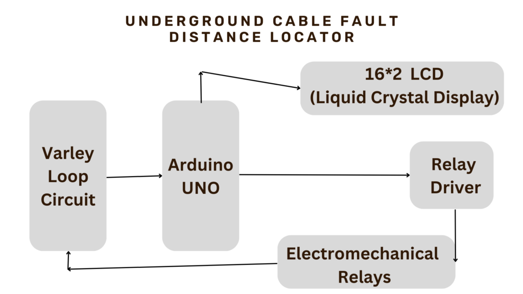
Block Diagram:

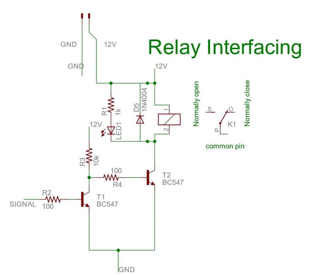
Circuits:-


Connect the Varley loop to the Relays and Microcontroller according to the pins mentioned in the Code. here we have shown the single relay but you can take 3 relay as our project required.
Components Required
Here are the essential components required for building the Underground Cable Fault Distance Locator:
Connecting Wires and Breadboard: Facilitate circuit connections.
Arduino UNO: The microcontroller forms the brain of the system, handling input and output operations.
16×2 LCD Display: Displays the fault location and distance from the source.
Relays: Used for switching operations.
Resistors and Capacitors: Help stabilize the circuit.
Diodes: Prevent backflow of current.
Transistors: Amplify signals in the circuit.
DC Power Supply: Powers the system components.
Testing and Calibration
After building the circuit and programming the Arduino, it’s crucial to calibrate the system. Calibration involves determining the cable’s velocity factor and the speed of the signal, which are necessary for accurately calculating the fault location.
How the Underground Cable Fault Distance Locator Works
This project operates based on the principle of Ohm’s Law and the variation in resistance caused by a fault in the cable. Here’s a step-by-step explanation:
- Voltage Division: A series of resistors represent the cable length. Faults are simulated by introducing a change in resistance.
- Fault Detection: When a fault occurs, the voltage across the corresponding segment changes.
- Arduino Processing: The Arduino reads these voltage changes and calculates the fault distance.
- Display Output: The fault distance is displayed on the 16×2 LCD screen.
- Relays: Activate based on fault location to isolate the faulty segment for repairs.
This design ensures precise fault detection and easy interpretation of results.
Building the Underground Cable Fault Locator
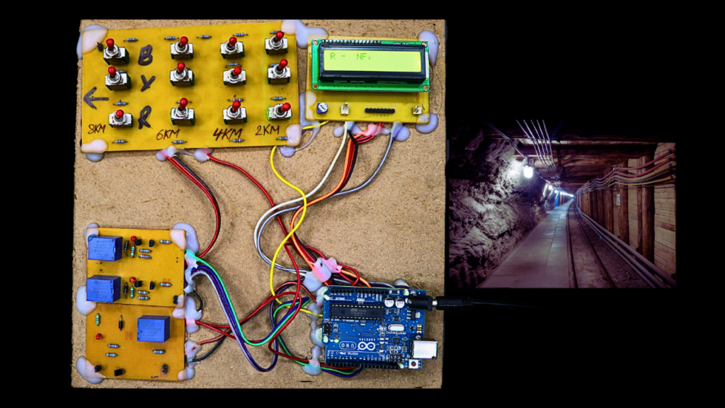
Constructing the Arduino-based cable fault locator involves assembling the hardware components, programming the Arduino microcontroller, and connecting the components to the cable.
Hardware Assembly:
Connect the Arduino board to the Varley loop circuit analog pin.
Connect the 16×2 LCD display to the Arduino board using jumper wires according to the circuits diagram.
Connect the relays pin in the Varley loop circuit to the Arduino board and control pins.
Connect the current-sensing resistors to the relays baord and the Arduino board’s ADC pins.
Connect the power supply to the Arduino board and the relays.
Software Programming:
Install the Arduino IDE software on your computer.
Write the Arduino sketch to control the relays, read voltage drop values, and calculate the fault location.
Upload the Arduino sketch to the Arduino board.
Code / Program of the project underground cable fault distance locator
/*
@circuitsbazaar
*/

#include <LiquidCrystal.h>
// initialize the library with the numbers of the interface pins
LiquidCrystal lcd(12, 11, 5, 4, 3, 2);


int sensorPin   = A0; // select the input pin for ldr
int sensorValue = 0; // variable to store the value coming from the sensor


void setup() {

  pinMode(8, OUTPUT); // Reelay 1
    pinMode(9, OUTPUT); // Reelay 2
      pinMode(10, OUTPUT); // Reelay 3

  digitalWrite(8, LOW);
    digitalWrite(9, HIGH);
      digitalWrite(10, HIGH);

Serial.begin(9600); //sets serial port for communication


  lcd.begin(16, 2);
  lcd.print("UNDERGROUND CABLE");
  lcd.setCursor(0, 1);
  lcd.print("FAULT LOCATOR");

  delay(1000);
  delay(1000);

}
void loop()
{


 lcd.clear();
  digitalWrite(8, LOW); // Low means relay on
    digitalWrite(9, HIGH);
      digitalWrite(10, HIGH);
       delay(350);

sensorValue = analogRead(sensorPin); // read the value from the sensor
Serial.println(sensorValue); //prints the values coming from the sensor on the screen

 if( (sensorValue >= 1000) )
{
     lcd.setCursor(0, 0);
      lcd.print("R -  NF,") ;
   Serial.print("R -  NF,") ;


 }

  else if( (sensorValue >= 890) && (sensorValue <= 920)  )
{
 Serial.print("R - 2KM,") ;
   lcd.setCursor(0, 0);
  lcd.print("R - 2KM,") ;
}
  else if( (sensorValue >= 870) && (sensorValue <= 880)  )
{
 Serial.print("R - 4KM,") ;
    lcd.setCursor(0, 0);
   lcd.print("R - 4KM,") ;
}
  else if( (sensorValue >= 800) && (sensorValue <= 825)  )
{
 Serial.print("R - 6KM,") ;
    lcd.setCursor(0, 0);
   lcd.print("R - 6KM,") ;
}
  else if( (sensorValue >= 670) && (sensorValue <= 688)  )
{
 Serial.print("R - 8KM,") ;
    lcd.setCursor(0, 0);
   lcd.print("R - 8KM,") ;
}
 delay(1500);

digitalWrite(8, HIGH);
    digitalWrite(9, LOW);
      digitalWrite(10, HIGH);
       delay(350);

sensorValue = analogRead(sensorPin); // read the value from the sensor
Serial.println(sensorValue); //prints the values coming from the sensor on the screen

 if( (sensorValue >= 1000) )
{

   Serial.print("Y -  NF") ;
    lcd.setCursor(8, 0);
    lcd.print(" Y -  NF,") ;
 }

  else if( (sensorValue >= 890) && (sensorValue <= 920)  )
{
  lcd.setCursor(8, 0);
 Serial.print("Y - 2KM,") ;
  lcd.print(" Y - 2KM,") ;
}
  else if( (sensorValue >= 870) && (sensorValue <= 880)  )
{
 Serial.print("Y - 4KM,") ;
 lcd.setCursor(8, 0);
   lcd.print(" Y - 4KM,") ;
}
  else if( (sensorValue >= 800) && (sensorValue <= 825)  )
{
 Serial.print("Y - 6KM,") ;
 lcd.setCursor(8, 0);
   lcd.print(" Y - 6KM,") ;
}
  else if( (sensorValue >= 670) && (sensorValue <= 688)  )
{
 Serial.print("Y - 8KM,") ;
 lcd.setCursor(8, 0);
   lcd.print(" Y - 8KM,") ;
}
 delay(1500);


digitalWrite(8, HIGH);
    digitalWrite(9, HIGH);
      digitalWrite(10, LOW);
       delay(350);

sensorValue = analogRead(sensorPin); // read the value from the sensor
Serial.println(sensorValue); //prints the values coming from the sensor on the screen

 if( (sensorValue >= 1000) )
{
  lcd.setCursor(5, 1);
   Serial.println("B -  NF") ;
    lcd.print("B -  NF") ;
 }

  else if( (sensorValue >= 890) && (sensorValue <= 920)  )
{
 Serial.println("B - 2KM") ;
 lcd.setCursor(5, 1);
  lcd.print("B - 2KM") ;
}
  else if( (sensorValue >= 870) && (sensorValue <= 880)  )
{
 Serial.println("B - 4KM") ;
 lcd.setCursor(5, 1);
   lcd.print("B - 4KM") ;
}
  else if( (sensorValue >= 800) && (sensorValue <= 825)  )
{
 Serial.println("B - 6KM") ;
 lcd.setCursor(5, 1);
   lcd.print("B - 6KM") ;
}
  else if( (sensorValue >= 670) && (sensorValue <= 688)  )
{
 Serial.println("B - 8KM") ;
 lcd.setCursor(5, 1);
   lcd.print("B - 8KM") ;
}
 delay(1500);


}
PCB Download Link for Underground Cable Fault Locator:
Click here
Cable Connection:
Connect one end of the cable to the Arduino board and the other end to the fault injection point.
Connect the voltage-sensing circuits to the respective cable segments using relays.
Using the Cable Fault Locator
Power on the Arduino board and the relays.
Press the ‘Start’ button to initiate the fault detection process.
The Arduino microcontroller will activate the relays one by one, measuring the voltage drop across each cable segment.
The fault location will be displayed on the LCD screen.
Limitations of Arduino-Based Cable Fault Locator
Accuracy: Accuracy depends on the calibration of the current-sensing resistors and the precision of the ADC.
Fault type: Can only detect short circuit faults; open circuit faults require additional techniques.
Applications
The Underground Cable Fault Locator can be employed in various sectors, such as:
- Power Distribution: Detect faults in power cables in urban or rural grids.
- Telecommunication: Identify issues in underground communication lines.
- Industrial Automation: Locate cable faults in industrial plants.
- Railways: Monitor underground cabling in railway signaling systems.
Safety Considerations
Working with high-voltage equipment and electrical circuits demands strict safety measures
Work in a controlled environment.
Disconnect power sources when making connections.
Use insulating materials and enclosures to prevent electrical hazards.
Keep bystanders away from the testing area
Advantages and Disadvantages
Advantages
- Cost-Effective: Uses affordable components like Arduino and relays.
- Accurate Fault Location: Provides precise fault distance, saving time and resources.
- Scalable: Can be adapted for longer cables or complex networks.
- Low Maintenance: Requires minimal upkeep once installed.
Disadvantages
- Simulation Limitations: Performance may vary based on cable types and environmental conditions.
- Distance Limitation: May require amplification for detecting faults in very long cables.
- Initial Setup: Requires careful calibration during the initial setup phase.
Future Scope
This project has immense potential for future upgrades:
- IoT Integration: Adding Internet of Things (IoT) capabilities for remote fault monitoring.
- Advanced Sensors: Incorporating high-precision sensors to improve accuracy.
- Mobile App Connectivity: Developing a companion app for displaying fault data.
- AI-Powered Insights: Using machine learning to predict potential faults before they occur.
Conclusion
The Underground Cable Fault Distance Locator Using Arduino is a smart and innovative project designed to address real-world challenges in cable maintenance. Its cost-effectiveness, accuracy, and scalability make it an ideal choice for engineering students and industry professionals.
By implementing this system, power and communication providers can significantly reduce downtime and maintenance costs, ensuring uninterrupted service delivery.
Conclusion
The Underground Cable Fault Locator project
This innovative project demonstrates the potential of technology to address real-world challenges and contributes to the maintenance and reliability of underground cable networks, ensuring that the world continues to run smoothly.
🛒 Buy Fully Assembled Project (H2)
If you are a student who wants to concentrate on understanding the working principle, fault analysis logic, relay operation, and viva preparation rather than assembling and debugging hardware, you can directly use the fully assembled Underground Cable Fault Distance Locator project available on Circuits Bazaar.

