Electronics Engineering Project Blogs
Innovative Quiz Buzzer / Fastest Fingerprint Project: A Scalable Engineering Solution for Quiz Competitions
Introduction
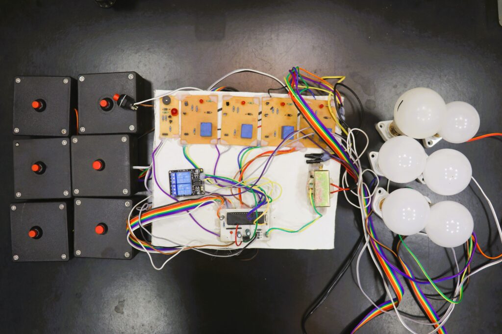
In the world of competitive quizzes and game shows, the Quiz Buzzer or Fastest Fingerprint System plays a crucial role. Whether it’s a small classroom competition or a large-scale event, an efficient and reliable buzzer system ensures that the fastest contestant is recognized instantly. In this project, I have designed a scalable Quiz Buzzer System using an 8051 microcontroller, which can support 4, 6, 8, or any number of candidates by increasing the input-output pins of the microcontroller. The system uses AC bulbs controlled via a relay module, a buzzer-LED module, and push buttons for each contestant.
This innovative project not only meets the requirements of quiz competitions but is also easy to expand and customize. Let’s dive into the detailed working, components, applications, and future scope of this project.
You can make any number of quiz buzzer like 4,8,10, etc. according to your requirement. you just need to add the relay modules and input units.
Working of the Quiz Buzzer System
The working of this Quiz Buzzer / Fastest Fingerprint Project is simple yet highly effective:
- Push Button Input: Each contestant is provided with a push button connected to the 8051 microcontroller. When a contestant presses their button, the microcontroller reads the input.
- Relay Activation: The microcontroller then sends a signal to the corresponding relay, which activates the connected AC bulb. This bulb remains on, indicating which contestant pressed their button first.
- Buzzer-LED Module: Simultaneously, the buzzer-LED module is activated, providing a visual and auditory signal that a button has been pressed.
- System Reset: After each round, the quizmaster can press the reset button to deactivate the buzzer, turn off the AC bulbs, and prepare the system for the next question.
The Quiz Buzzer System is scalable. For a 4, 6, or 8-candidate system, simply connect more push buttons, relays, and bulbs to the available pins of the 8051 microcontroller.
Video Demonstration of the Project :-
Project Kit:- Click Here OR Contact at +91-8571964488 , +91-8684884488 ( Call or Whatsapp )
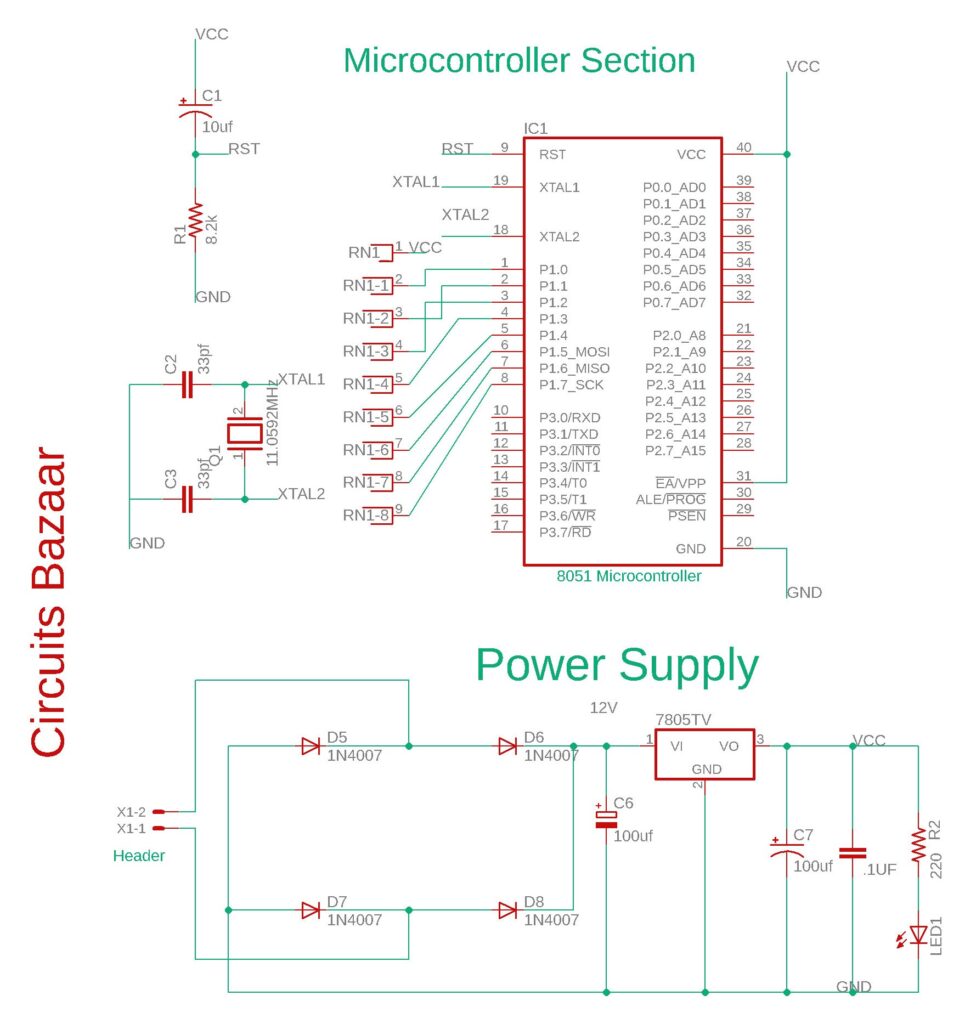
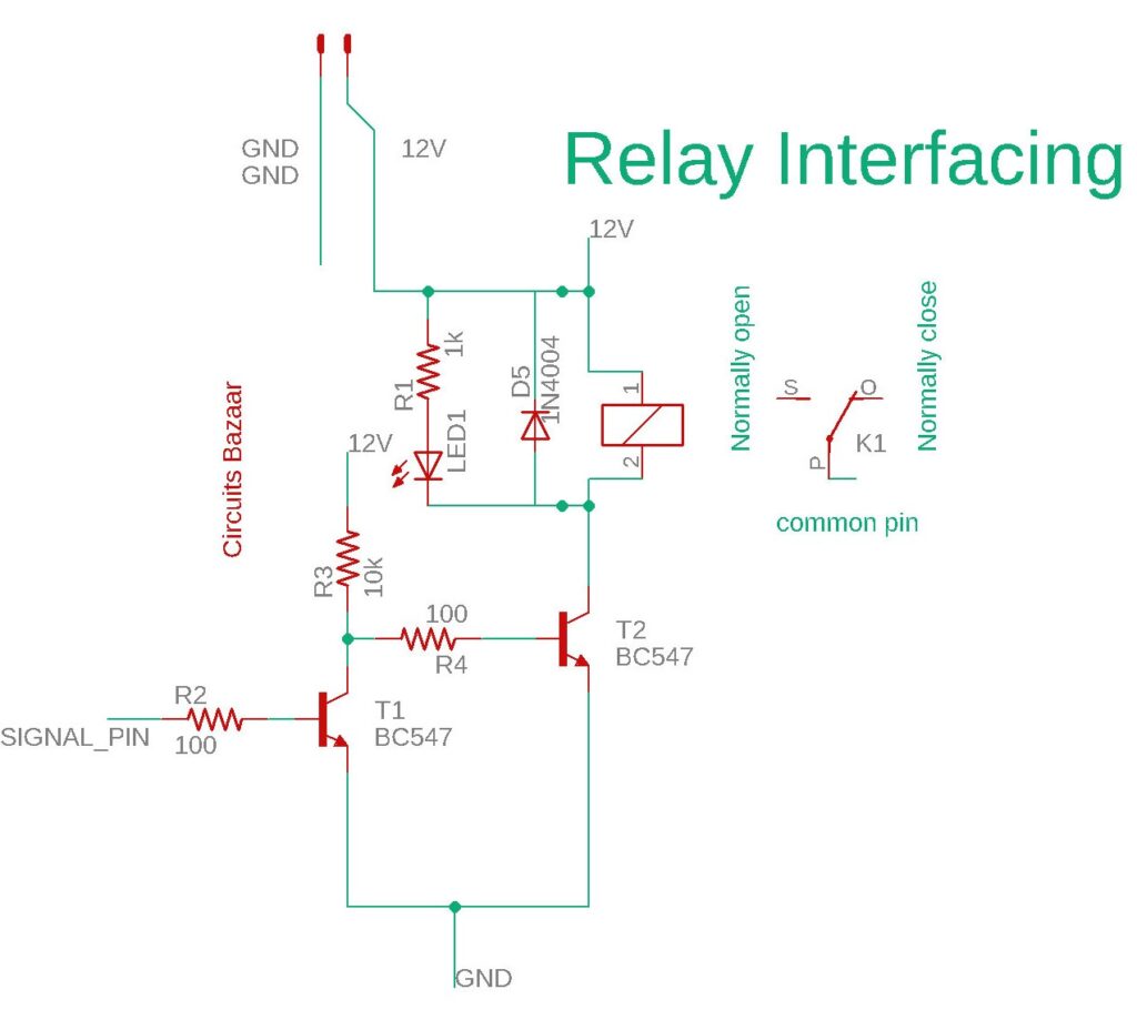
Circuits Diagram :-
8051 microcontroller and power supply section :

Relay Driver section to drive the AC Bulbs

Instead of using this relay driver , you can use ready made relay driver modules available online.
you can build your own circuit by following the below pinout connection for your Quiz Buzzer / Fastest Fingerprint project based on the code you’ve provided. This explains how the pins of the 8051 microcontroller are connected to the buzzer, push buttons, and relays for controlling the AC bulbs.
Microcontroller Pin Connections
- Push Button Inputs (Candidates’ Buttons):
- Pin P1.0 → Push Button 1 (Candidate 1)
- Pin P1.1 → Push Button 2 (Candidate 2)
- Pin P1.2 → Push Button 3 (Candidate 3)
- Pin P1.3 → Push Button 4 (Candidate 4)
- Pin P1.4 → Push Button 5 (Candidate 5)
- Pin P1.5 → Push Button 6 (Candidate 6)
- Buzzer:
- Pin P1.7 → Buzzer Module
- Reset Button:
- Pin P1.6 → Reset Button
- Relay Outputs (Controlling AC Bulbs):
- Pin P2.0 → Relay 1 (Candidate 1)
- Pin P2.1 → Relay 2 (Candidate 2)
- Pin P2.2 → Relay 3 (Candidate 3)
- Pin P2.3 → Relay 4 (Candidate 4)
- Pin P2.4 → Relay 5 (Candidate 5)
- Pin P2.5 → Relay 6 (Candidate 6)
Detailed Connections Summary:
- Push Buttons (for each candidate):
- Button 1 → P1.0
- Button 2 → P1.1
- Button 3 → P1.2
- Button 4 → P1.3
- Button 5 → P1.4
- Button 6 → P1.5
- Relays (for controlling AC bulbs):
- Relay 1 (Candidate 1’s AC bulb) → P2.0
- Relay 2 (Candidate 2’s AC bulb) → P2.1
- Relay 3 (Candidate 3’s AC bulb) → P2.2
- Relay 4 (Candidate 4’s AC bulb) → P2.3
- Relay 5 (Candidate 5’s AC bulb) → P2.4
- Relay 6 (Candidate 6’s AC bulb) → P2.5
- Buzzer:
- Buzzer → P1.7
- Reset Button:
- Reset Button → P1.6
Power Supply:
- The relays and the buzzer module will require external power, as controlling AC devices involves higher voltages than the microcontroller can handle.
- The 8051 microcontroller should be powered by a regulated 5V power supply, which you are providing through a 7805 voltage regulator connected to a 12V step-down transformer with rectifier and filtering capacitors.
Project Code
The heart of our Quiz Buzzer system is the code running on the 8051 microcontroller. Here’s a brief overview of the main functions:
// This is the code for the project of 6 candidates quiz buzzer

#include <reg51.h> // Include the header file for the 8051 microcontroller

// Define ports for easy reference
#define dataport P0 // Port 0 can be used to connect an LCD, but it's not used in this project
#define key P3      // Port 3 can be used for additional keys or functionalities

// Define single-bit (sbit) variables for input push buttons connected to Port 1
sbit in1 = P1^0; // Push button input for Candidate 1 connected to P1.0
sbit in2 = P1^1; // Push button input for Candidate 2 connected to P1.1
sbit in3 = P1^2; // Push button input for Candidate 3 connected to P1.2
sbit in4 = P1^3; // Push button input for Candidate 4 connected to P1.3
sbit in5 = P1^4; // Push button input for Candidate 5 connected to P1.4
sbit in6 = P1^5; // Push button input for Candidate 6 connected to P1.5

// Define single-bit variables for the buzzer and reset button connected to Port 1
sbit buz = P1^7;   // Buzzer connected to P1.7
sbit reset = P1^6; // Reset button connected to P1.6

// Define single-bit variables for relay outputs connected to Port 2
sbit rl1 = P2^0; // Relay for Candidate 1's AC bulb connected to P2.0
sbit rl2 = P2^1; // Relay for Candidate 2's AC bulb connected to P2.1
sbit rl3 = P2^2; // Relay for Candidate 3's AC bulb connected to P2.2
sbit rl4 = P2^3; // Relay for Candidate 4's AC bulb connected to P2.3
sbit rl5 = P2^4; // Relay for Candidate 5's AC bulb connected to P2.4
sbit rl6 = P2^5; // Relay for Candidate 6's AC bulb connected to P2.5

// Function to create a delay (approximately)
void delay(unsigned int msec) // Time delay function
{
    int i, j; // Loop counters
    for(i = 0; i < msec; i++) // Outer loop for milliseconds
        for(j = 0; j < 1275; j++); // Inner loop for creating delay
}

// Main function where the program execution starts
void main()
{
    // Initialize all relay outputs to HIGH (inactive state)
    rl1 = rl2 = rl3 = rl4 = rl5 = rl6 = 1;

    // Initialize the buzzer to HIGH (inactive state)
    buz = 1;

    // Enter an infinite loop to continuously check for button presses
    while(1)
    {
        // Check if Candidate 1's button is pressed (active LOW)
        if(in1 == 0)
        {
            delay(10); // Debounce delay
            if(in1 == 0) // Confirm the button is still pressed
            {
                rl1 = 0;   // Activate Relay 1 to turn on Candidate 1's AC bulb
                buz = 0;    // Activate the buzzer and LED (assuming active LOW)
                while(reset == 1); // Wait until the reset button is pressed (active LOW)
                buz = 1;    // Deactivate the buzzer and LED
                rl1 = 1;    // Deactivate Relay 1 to turn off the AC bulb
            }
        }

        // Check if Candidate 2's button is pressed
        if(in2 == 0)
        {
            delay(10); // Debounce delay
            if(in2 == 0) // Confirm the button is still pressed
            {
                rl2 = 0;   // Activate Relay 2 to turn on Candidate 2's AC bulb
                buz = 0;    // Activate the buzzer and LED
                while(reset == 1); // Wait until the reset button is pressed
                buz = 1;    // Deactivate the buzzer and LED
                rl2 = 1;    // Deactivate Relay 2 to turn off the AC bulb
            }
        }

        // Check if Candidate 3's button is pressed
        if(in3 == 0)
        {
            delay(10); // Debounce delay
            if(in3 == 0) // Confirm the button is still pressed
            {
                rl3 = 0;   // Activate Relay 3 to turn on Candidate 3's AC bulb
                buz = 0;    // Activate the buzzer and LED
                while(reset == 1); // Wait until the reset button is pressed
                buz = 1;    // Deactivate the buzzer and LED
                rl3 = 1;    // Deactivate Relay 3 to turn off the AC bulb
            }
        }

        // Check if Candidate 4's button is pressed
        if(in4 == 0)
        {
            delay(10); // Debounce delay
            if(in4 == 0) // Confirm the button is still pressed
            {
                rl4 = 0;   // Activate Relay 4 to turn on Candidate 4's AC bulb
                buz = 0;    // Activate the buzzer and LED
                while(reset == 1); // Wait until the reset button is pressed
                buz = 1;    // Deactivate the buzzer and LED
                rl4 = 1;    // Deactivate Relay 4 to turn off the AC bulb
            }
        }

        // Check if Candidate 5's button is pressed
        if(in5 == 0)
        {
            delay(10); // Debounce delay
            if(in5 == 0) // Confirm the button is still pressed
            {
                rl5 = 0;   // Activate Relay 5 to turn on Candidate 5's AC bulb
                buz = 0;    // Activate the buzzer and LED
                while(reset == 1); // Wait until the reset button is pressed
                buz = 1;    // Deactivate the buzzer and LED
                rl5 = 1;    // Deactivate Relay 5 to turn off the AC bulb
            }
        }

        // Check if Candidate 6's button is pressed
        if(in6 == 0)
        {
            delay(10); // Debounce delay
            if(in6 == 0) // Confirm the button is still pressed
            {
                rl6 = 0;   // Activate Relay 6 to turn on Candidate 6's AC bulb
                buz = 0;    // Activate the buzzer and LED
                while(reset == 1); // Wait until the reset button is pressed
                buz = 1;    // Deactivate the buzzer and LED
                rl6 = 1;    // Deactivate Relay 6 to turn off the AC bulb
            }
        }
    }
}
This program effectively manages a quiz buzzer system where multiple candidates can press their buttons to signal their responses. The microcontroller detects the first button press, activates the corresponding AC bulb and buzzer/LED module, and waits for a reset to prepare for the next question. The use of relays allows for controlling high-voltage AC bulbs safely, while the 8051 microcontroller ensures reliable and timely response detection.
Applications of the Quiz Buzzer System
- Quiz Competitions: The primary use of this project is in quiz competitions to identify the fastest respondent.
- Game Shows: It can also be used in game shows where the fastest response wins a reward.
- School and College Events: Ideal for educational institutions, this project adds professionalism to classroom quizzes and competitions.
- Corporate Training: It can be used in corporate training sessions to engage participants in competitive activities.
Advantages of the Quiz Buzzer System
- Scalable Design: This system can be easily expanded to support any number of participants by increasing the microcontroller’s input and output pins.
- Easy to Implement: Using basic electronic components like push buttons, relays, and bulbs makes this system straightforward to build.
- Low Cost: The components used are readily available and affordable, making it a budget-friendly solution.
- Reliable Performance: The 8051 microcontroller ensures that the system is reliable and fast, with minimal delay in response time.
- User-Friendly: The system is easy for both contestants and quizmasters to use, with clear visual and auditory signals.
Disadvantages of the Quiz Buzzer System
- Wired System: The system relies on wired connections, which can become cumbersome in larger setups.
- Limited Range: Since the push buttons are connected directly to the microcontroller, participants need to be within a certain range of the system.
Future Scope
- Wireless Quiz Buzzer: A future version of this system could incorporate wireless technology, allowing contestants to participate from a distance without the need for physical wires.
- LCD Display: Adding an LCD screen to display contestant numbers or timings could enhance the system’s functionality.
- Data Logging: Future iterations could include data logging capabilities to record which contestant pressed the button first for future reference.
- Battery-Powered Version: Creating a portable, battery-powered version of the system could make it more convenient for outdoor events.
Conclusion
The Quiz Buzzer / Fastest Fingerprint Project is an essential tool for quiz competitions, game shows, and educational activities. With a simple yet effective design, this project provides a reliable and scalable solution that can be adapted to support any number of contestants. The use of 8051 microcontroller, relay module, and AC bulbs ensures that the system is both functional and easy to implement. By exploring future possibilities like wireless technology and data logging, this project has the potential to evolve into a more advanced and sophisticated system.
With a clear understanding of how this project works, its components, and its applications, anyone interested in quiz competitions or game show setups can build and expand upon this Quiz Buzzer System.
Project Kit:- Click Here OR Contact at +91-8571964488 , +91-8684884488 ( Call or Whatsapp )

