


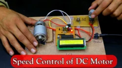


DC Motor Speed Control using Arduino PWM and TIP122 Transistor with LCD Display
 6")

Original price was: ₹3,800.00.₹2,900.00Current price is: ₹2,900.00.
🧠 DC Motor Speed Control using Arduino PWM and TIP122 Transistor is an innovative project designed to control the speed of a DC motor through Pulse Width Modulation (PWM). The Arduino (ATmega328 microcontroller) reads data from a potentiometer, adjusts the PWM signal, and displays the real-time motor speed on a 16×2 LCD. The TIP122 transistor acts as a current amplifier, ensuring the motor receives sufficient current for smooth operation. This project demonstrates the working of PWM in motor speed regulation, making it an excellent learning tool for B.Tech, Diploma, and hobby students interested in embedded systems and industrial automation. The entire setup runs on a 12 V 1 A adapter and includes all essential documentation – report, PPT, and working videos.
149 in stock
⚙️ Introduction
🚀 DC Motor Speed Control using Arduino PWM and TIP122 Transistor is a powerful and practical electronics project that helps you understand how to efficiently control DC motor speed using Pulse Width Modulation. In this project, an Arduino-based circuit is designed to adjust motor speed according to the input from a potentiometer while simultaneously displaying the motor speed on an LCD. This DC Motor Speed Control using Arduino PWM and TIP122 Transistor project demonstrates how to vary speed precisely using a transistor-based PWM circuit.
The TIP122 transistor plays a crucial role as a Darlington pair transistor, which amplifies the low-current PWM signal from the Arduino into a high-current output capable of driving a DC motor. This combination of microcontroller, transistor, and LCD display creates a compact yet efficient control system suitable for both academic learning and industrial applications.
🔋 Working Principle
🧠 The working principle of this project revolves around Pulse Width Modulation (PWM). The Arduino generates a PWM signal whose duty cycle determines the effective voltage across the DC motor. The DC Motor Speed Control using Arduino PWM and TIP122 Transistor circuit processes the potentiometer signal and converts it into a stable PWM output.
Here’s how it works step-by-step:
The potentiometer sends an analog signal to the Arduino’s analog input pin.
The Arduino processes this signal and converts it into a PWM output using its digital output pin.
The PWM signal is fed to the base of the TIP122 transistor, which acts as a switch and amplifier.
The TIP122 transistor controls the amount of current flowing from the power supply (12 V 1 A adapter) to the motor.
The 16×2 LCD display shows the real-time motor speed or PWM value, providing user feedback.
This system ensures precise speed control without complex circuitry, making it ideal for understanding PWM concepts in embedded electronics.
🧰 Components Used
✍️ The core components of this project include:
Arduino ATmega328 Microcontroller (on PCB)
TIP122 NPN Darlington Transistor
16×2 LCD Display
10 kΩ Potentiometer
12 V 1 A DC Adapter
DC Motor (12 V rated)
Resistors and Capacitors for circuit stabilization
Custom PCB Board designed for the project
Each component plays a critical role — the TIP122 amplifies current, the LCD displays values, and the potentiometer allows real-time speed adjustment.
🧩 Circuit Description
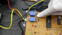
The circuit is built around the ATmega328 microcontroller, which is the same chip used in the Arduino UNO. Instead of mounting the full Arduino UNO board, the ATmega328 chip is removed and placed on a custom PCB that has its own power supply section, LCD interface, and transistor driver circuit.
The PWM output pin from the ATmega328 is connected to the base of the TIP122 transistor via a current-limiting resistor. The motor is connected between the collector of the TIP122 and the 12 V supply. The emitter is grounded.
This setup ensures that the transistor controls motor speed according to the PWM signal’s duty cycle. The LCD (connected in 4-bit mode) displays values such as “Speed = 120” or similar based on potentiometer input.
🧭 Applications
The DC Motor Speed Control using Arduino PWM and TIP122 Transistor project is perfect for students and engineers learning automation.
🔹 Industrial Automation: DC motor control in conveyors and automation lines.
🔹 Educational Demonstration: Ideal for demonstrating PWM and transistor amplification concepts.
🔹 Robotics: Used for controlling robotic wheels or actuators.
🔹 Research Projects: Useful for developing microcontroller-based speed control modules.
🔹 DIY and Hobby: Perfect for Arduino learners and electronic enthusiasts.
🚀 Future Scope
The concept can be extended by:
✅ Integrating feedback using rotary encoders for precise speed regulation.
✅ Adding Bluetooth or IoT modules for wireless motor control.
✅ Implementing closed-loop control with PID algorithms.
✅ Using MOSFETs or dedicated motor-driver ICs for higher efficiency.
This makes it not only a great academic project but also a foundation for real-world industrial motor control systems.
🔗 Internal Links
👉 Electrical Engineering Projects
👉 Electronics Engineering Projects
👉 Best Seller Engineering Projects
👉 Hardware Projects Without Coding
👉 Engineering Project Blog
📦 Read the Complete Blog of DC Motor Speed Control Project
👉 DC Motor Speed Control using Arduino PWM and TIP122 Blog
✅ Summary:
This project explains how DC motor speed control using Arduino PWM and TIP122 transistor works — from circuit design and code logic to real-time display. It’s a compact, educational, and industrially relevant project suitable for anyone learning embedded systems or automation. Overall, this DC Motor Speed Control using Arduino PWM and TIP122 Transistor system is ideal for both industrial and educational learning.
🎥 Project Demonstration Video
🎬 Hindi Demonstration 👇
🎬 English Demonstration 👇
🌐 External Resource Link
👉 Electronics Tutorials — Working of Darlington Pair Transistor (TIP122)
❓ Frequently Asked Questions
🧠 Q1. How does the DC Motor Speed Control using Arduino PWM and TIP122 Transistor work?
A. The project uses the Arduino’s PWM output to control the voltage supplied to the DC motor. A potentiometer adjusts the PWM duty cycle, and the TIP122 transistor amplifies the current, enabling precise speed control. The LCD shows real-time motor speed, helping users visualize changes instantly. This project demonstrates a perfect blend of analog control and digital processing.
⚙️ Q2. Why is the TIP122 transistor used instead of directly connecting the motor to Arduino?
A. The Arduino can only provide a small amount of current (about 20–40 mA), which is insufficient to drive a DC motor. The TIP122 Darlington transistor acts as a current amplifier and switch, allowing the motor to run safely on higher current from an external 12V adapter. Without the TIP122, the motor might overload or damage the Arduino board.
🧩 Q3. Can I use any type of DC motor for this project?
A. Yes, you can use any small to medium-sized 12V DC motor. However, ensure that the motor’s current rating does not exceed the transistor’s capacity (around 5A for TIP122). For higher torque motors, you can replace the transistor with a MOSFET like IRF540N or use an L298N motor driver module for more robust control.
📈 Q4. What are the practical applications of this project?
A. This project is highly useful in industrial automation, conveyor belt systems, robotic arms, and educational setups. It’s a hands-on example for learning PWM, transistor amplification, and embedded control. Many students also use it as a B.Tech mini or major project, as it’s simple, low-cost, and conceptually rich.
🚀 Q5. Can this project be upgraded for advanced learning or IoT integration?
A. Absolutely! You can upgrade this setup by adding sensors like rotary encoders for closed-loop feedback, or integrating Wi-Fi/Bluetooth modules (ESP8266 or HC-05) for wireless control. Additionally, the system can be enhanced using a PID control algorithm for more accurate speed regulation, making it suitable for IoT-based motor control applications.
| Weight | 3 kg |
|---|---|
| Dimensions | 35 × 35 × 8 cm |
Related products
Electrical Engineering Projects
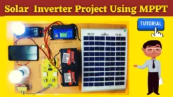
Advanced MPPT Based Solar Inverter Project for Engineering Students
8051 Microcontroller Based Projects
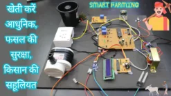
Smart Farming Management System Project for Electrical Engineering


Electrical Engineering Projects
Automatic Wireless Controlled Smart Floor Cleaning Robot – 8051 Based Engineering Project
Electrical Engineering Projects
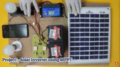
MPPT Hybrid Solar Inverter Project – Dual Solar & AC Charging System
8051 Microcontroller Based Projects


Best Selling Engineering Projects
Automatic Three Phase Changer Project Using Relay Logic | Electrical Engineering Project


Arduino Based Projects
Border Intrusion Detection System Using Arduino and GSM Wireless Network – Innovative Army Project