Electronics Engineering Project Blogs
POV 8 LED-Based Display using BLDC Motor and Arduino Uno/Nano – Complete Guide with Code and Circuit Diagrams
1. Introduction
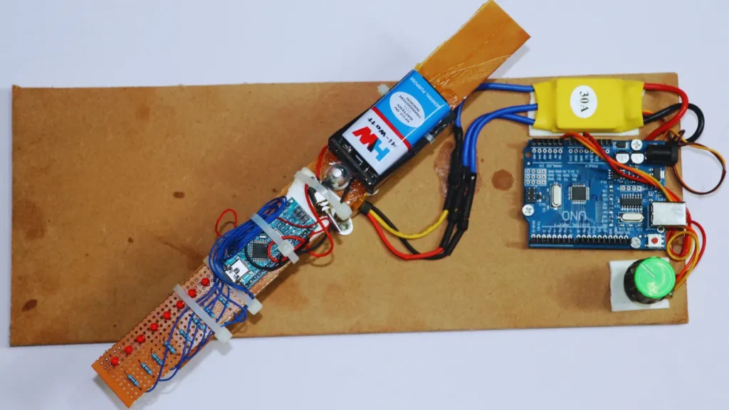
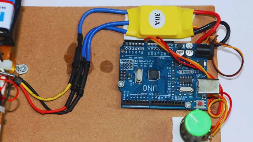
In this project, we will create a POV (Persistence of Vision) 8 LED-Based Display using an Arduino Uno, Arduino Nano, and a BLDC motor. The project demonstrates how to create a spinning LED display that shows text or patterns using the principle of persistence of vision. This project is divided into two main sections:
- BLDC Motor Speed Control – Using Arduino Uno, an ESC (Electronic Speed Controller), and a 10k potentiometer to control the motor’s speed.
- POV Display – Using Arduino Nano and 8 LEDs to create a spinning display that shows a text message like “JS RANA.”
The combination of Arduino Uno and Nano makes this project versatile and easy to modify for displaying different patterns or text. This project is perfect for electronics hobbyists, engineering students, and those looking to understand the basics of BLDC motor control and LED matrix displays.
2. Components Used
Here are the key components used in the project:
| Component | Description |
|---|---|
| Arduino Uno | Used to control the BLDC motor speed using ESC and potentiometer. |
| Arduino Nano | Used to drive the 8 LEDs for displaying text. |
| BLDC Motor (1400 KV) | Used for rotation to create POV effect. |
| ESC (30A) | Electronic Speed Controller for controlling the BLDC motor. |
| 10k Potentiometer | Used to adjust the motor speed. |
| 8 LEDs | To create the POV display. |
| Resistors | For limiting current through LEDs. |
| Wires and Connectors | For making circuit connections. |
| 9V Battery | Power source for Arduino Nano and LEDs. |
| 12V Power Supply | Power source for BLDC motor and ESC. |
3. Block Diagram
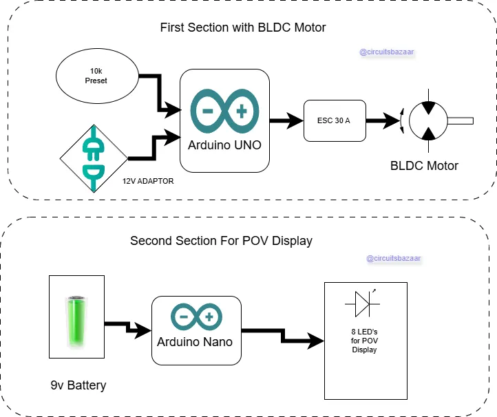
- BLDC Motor Speed Control – Arduino Uno → Potentiometer → ESC → BLDC Motor
- POV Display – Arduino Nano → LEDs → Display Message
4. Circuit Diagram
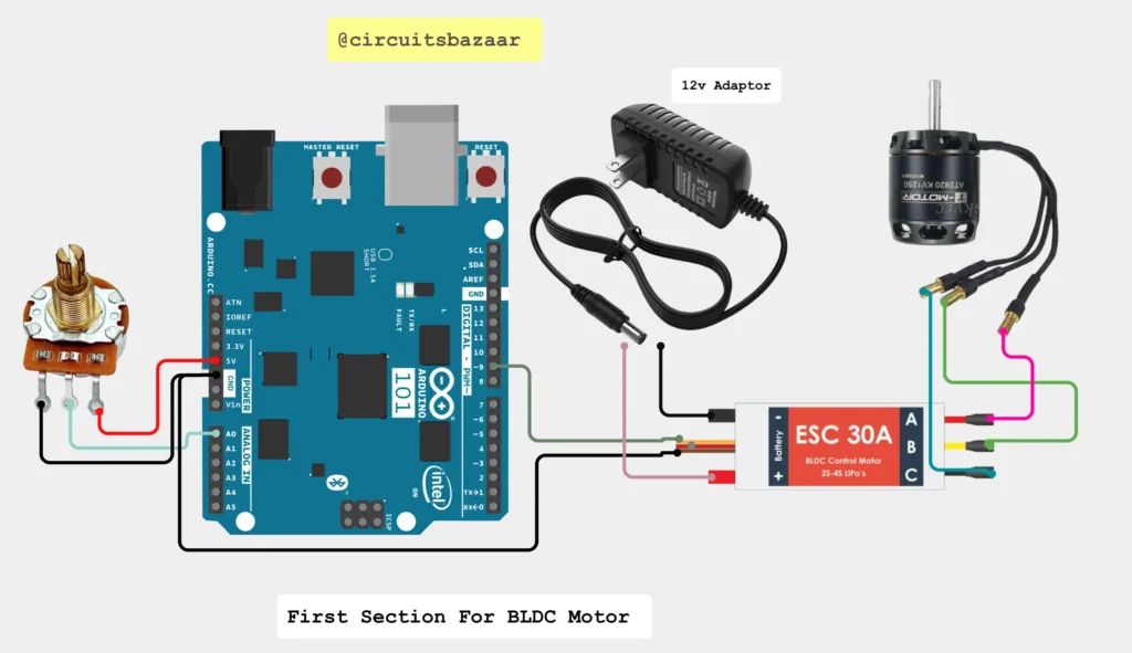
- BLDC Motor Control Circuit
- POV Display Circuit
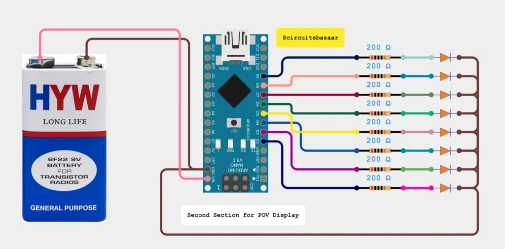
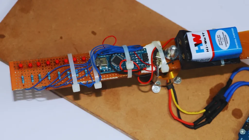
5. Working Principle
The project works based on the principle of Persistence of Vision (POV), where the human eye retains an image for a short period even after the object has disappeared. By rotating LEDs rapidly and turning them on/off in a specific pattern, the human eye perceives them as a static image or text.
- BLDC Motor Speed Control:
- The Arduino Uno reads the potentiometer’s value and sends a signal to the ESC.
- The ESC adjusts the motor speed based on the input signal.
- The BLDC motor rotates the LED structure at a constant speed.
- POV Display:
- The Arduino Nano sends signals to the LEDs based on pre-defined text patterns.
- As the motor rotates the LEDs, the LEDs blink in a sequence that forms readable text due to POV.
- Adjusting the speed ensures that the text remains readable without distortion.
Video Demonstration
6. Code for BLDC Motor Speed Control
Here’s the code for controlling the BLDC motor speed using an ESC and potentiometer:
#include <Servo.h>

Servo esc;  // Create a servo object for ESC

int potPin = A0;  // Potentiometer connected to A0
int escPin = 9;   // ESC signal connected to pin 9
int potValue;     // Variable to store potentiometer value

void setup() {
    esc.attach(escPin);  // Attach ESC to pin 9
}

void loop() {
    potValue = analogRead(potPin);  // Read potentiometer value (0-1023)
    int speed = map(potValue, 0, 1023, 1000, 2000);  // Map to ESC range (1000-2000us)

    esc.writeMicroseconds(speed);  // Send signal to ESC
    delay(10);  // Small delay for stability
}
Explanation:
- The
Servolibrary is used to control the ESC using PWM signals. - The potentiometer value is read and mapped to a range of 1000 to 2000 microseconds, which is the standard input range for ESC.
- The
esc.writeMicroseconds()function sends the mapped value to the ESC, which controls the motor speed.
7. Code for Testing LEDs
This code will test whether all LEDs are working by turning them on one by one:
#define NUM_LEDS 8
const int ledPins[NUM_LEDS] = {2, 3, 4, 5, 6, 7, 8, 9};

void setup() {
    for (int i = 0; i < NUM_LEDS; i++) {
        pinMode(ledPins[i], OUTPUT);
    }
}

void loop() {
    for (int i = 0; i < NUM_LEDS; i++) {
        digitalWrite(ledPins[i], HIGH);
        delay(200);
        digitalWrite(ledPins[i], LOW);
    }
    delay(500);
}
Explanation:
- All LED pins are defined and set as outputs.
- LEDs are turned on and off sequentially with a delay to test the circuit.
8. Code for POV Display
Here’s the code that displays text using the POV effect. This example will display “JS RANA”:
int A[] = {1,1,1,1,1,1,1,1, 1,0,0,1,0,0,0,0, 1,0,0,1,0,0,0,0, 1,0,0,1,0,0,0,0, 1,1,1,1,1,1,1,1};
int N[] = {1,1,1,1,1,1,1,1, 0,0,1,0,0,0,0,0, 0,0,0,1,1,0,0,0, 0,0,0,0,0,1,0,0, 1,1,1,1,1,1,1,1};
int S[] = {0,1,1,1,0,0,0,1, 1,0,0,0,1,0,0,1, 1,0,0,0,1,0,0,1, 1,0,0,0,1,0,0,1, 1,0,0,0,1,1,1,0};
int _[] = {0,0,0,0,0,0,0,0, 0,0,0,0,0,0,0,0, 0,0,0,0,0,0,0,0, 0,0,0,0,0,0,0,0, 0,0,0,0,0,0,0,0};
int J[] = {0,0,0,0,0,1,1,0, 0,0,0,0,1,0,0,1, 0,0,0,0,0,0,0,1, 0,0,0,0,0,0,0,1, 1,1,1,1,1,1,1,0};
int R[] = {1,1,1,1,1,1,1,1, 1,0,0,1,1,0,0,0, 1,0,0,1,0,1,0,0, 1,0,0,1,0,0,1,0, 0,1,1,0,0,0,0,1};

int* alpha[] = {J, S, _, R, A, N, A}; // Define the message to display

int letterSpace;
int dotTime;

void setup() {
    Serial.begin(9600);

    // Setting the LED pins as OUTPUT
    for (int i = 2; i < 10; i++) {
        pinMode(i, OUTPUT);
    }

    // Defining the time gap between letters
    letterSpace = 6;
    dotTime = 1;
}

void printLetter(int letter[]) {
    for (int y = 0; y < 8; y++) {
        digitalWrite(y + 2, letter[y]);
    }
    delay(dotTime);

    for (int y = 0; y < 8; y++) {
        digitalWrite(y + 2, letter[y + 8]);
    }
    delay(dotTime);

    for (int y = 0; y < 8; y++) {
        digitalWrite(y + 2, letter[y + 16]);
    }
    delay(dotTime);

    for (int y = 0; y < 8; y++) {
        digitalWrite(y + 2, letter[y + 24]);
    }
    delay(dotTime);

    for (int y = 0; y < 8; y++) {
        digitalWrite(y + 2, letter[y + 32]);
    }
    delay(dotTime);

    // Turn off LEDs to create a gap between letters
    for (int y = 0; y < 8; y++) {
        digitalWrite(y + 2, 0);
    }
    delay(letterSpace);
}

void loop() {
    // Loop through the message and display each letter
    for (int i = 0; i < sizeof(alpha) / sizeof(alpha[0]); i++) {
        printLetter(alpha[i]);
    }
}
Explanation:
- The LED matrix is controlled by defining patterns for each letter (as a binary matrix).
- The
alpha[]array holds the sequence of letters to be displayed. - The
printLetter()function sends data to the LEDs row-by-row to light up the correct pattern. - The
delay(dotTime)creates a consistent timing for each row to give a readable POV effect. - A small delay is added between letters to ensure clarity while reading the text.
9. How POV Works in the Code
- The human eye retains an image for approximately 1/16th of a second.
- By rotating the LED strip at a high speed and controlling the on/off pattern of LEDs using Arduino, the text appears stationary.
- The timing and sequence of LEDs turning on/off is the key to forming readable text.
- The
dotTimeandletterSpacevariables control the timing of the display. - Adjusting the motor speed will affect the text clarity, so the speed needs to be stable.
Code for any name Display
 int NUMBER9[]={1,1,1,1,0,0,0,1, 1,0,0,1,0,0,0,1, 1,0,0,1,0,0,0,1, 1,0,0,1,0,0,0,1, 1,1,1,1,1,1,1,1};
 int NUMBER8[]={0,1,1,0,1,1,1,0, 1,0,0,1,0,0,0,1, 1,0,0,1,0,0,0,1, 1,0,0,1,0,0,0,1, 0,1,1,0,1,1,1,0};
 int NUMBER7[]={1,0,0,0,0,0,0,0, 1,0,0,0,1,0,0,0, 1,0,0,0,1,0,0,0, 1,0,0,1,1,1,1,1, 1,1,1,0,1,0,0,0};
 int NUMBER6[]={1,1,1,1,1,1,1,1, 1,0,0,0,1,0,0,1, 1,0,0,0,1,0,0,1, 1,0,0,0,1,0,0,1, 1,0,0,0,1,1,1,1};
 int NUMBER5[]={1,1,1,1,1,0,0,1, 1,0,0,0,1,0,0,1, 1,0,0,0,1,0,0,1, 1,0,0,0,1,0,0,1, 1,0,0,0,1,1,1,1};
 int NUMBER2[]= {1,0,0,0,0,0,1,1, 1,0,0,0,0,1,0,1, 1,0,0,0,1,0,0,1, 1,0,0,1,0,0,0,1, 0,1,1,0,0,0,0,1};
 int NUMBER1[]= {0,0,1,0,0,0,0,0, 0,1,0,0,0,0,0,0, 1,1,1,1,1,1,1,1, 0,0,0,0,0,0,0,0, 0,0,0,0,0,0,0,0};
 int NUMBER0[]= {1,1,1,1,1,1,1,1, 1,0,0,0,0,0,0,1, 1,0,0,0,0,0,0,1, 1,0,0,0,0,0,0,1, 1,1,1,1,1,1,1,1};

 int _[] = {0,0,0,0,0,0,0,0, 0,0,0,0,0,0,0,0, 0,0,0,0,0,0,0,0, 0,0,0,0,0,0,0,0, 0,0,0,0,0,0,0,0};
 int A[] = {1,1,1,1,1,1,1,1, 1,0,0,1,0,0,0,0, 1,0,0,1,0,0,0,0, 1,0,0,1,0,0,0,0, 1,1,1,1,1,1,1,1};
 int B[] = {1,1,1,1,1,1,1,1, 1,0,0,1,0,0,0,1, 1,0,0,1,0,0,0,1, 1,0,0,1,0,0,0,1, 0,1,1,0,1,1,1,0};
 int C[] = {0,0,1,1,1,1,0,0, 0,1,0,0,0,0,1,0, 1,0,0,0,0,0,0,1, 1,0,0,0,0,0,0,1, 1,0,0,0,0,0,0,1};
 int D[] = {1,1,1,1,1,1,1,1, 1,0,0,0,0,0,0,1, 1,0,0,0,0,0,0,1, 0,1,0,0,0,0,1,0, 0,0,1,1,1,1,0,0};
 int E[] = {1,1,1,1,1,1,1,1, 1,0,0,1,0,0,0,1, 1,0,0,1,0,0,0,1, 1,0,0,1,0,0,0,1, 1,0,0,1,0,0,0,1};
 int F[] = {1,1,1,1,1,1,1,1, 1,0,0,1,0,0,0,0, 1,0,0,1,0,0,0,0, 1,0,0,1,0,0,0,0, 1,0,0,1,0,0,0,0};
 int G[] = {0,1,1,1,1,1,1,1, 1,0,0,0,0,0,0,1, 1,0,0,0,1,0,0,1, 1,0,0,0,1,0,0,1, 1,0,0,0,1,1,1,0};
 int H[] = {1,1,1,1,1,1,1,1, 0,0,0,0,1,0,0,0, 0,0,0,0,1,0,0,0, 0,0,0,0,1,0,0,0, 1,1,1,1,1,1,1,1};
 int I[] = {1,0,0,0,0,0,0,1, 1,0,0,0,0,0,0,1, 1,1,1,1,1,1,1,1, 1,0,0,0,0,0,0,1, 1,0,0,0,0,0,0,1};
 int J[] = {0,0,0,0,0,1,1,0, 0,0,0,0,1,0,0,1, 0,0,0,0,0,0,0,1, 0,0,0,0,0,0,0,1, 1,1,1,1,1,1,1,0};
 int K[] = {1,1,1,1,1,1,1,1, 0,0,0,1,1,0,0,0, 0,0,1,0,0,1,0,0, 0,1,0,0,0,0,1,0, 1,0,0,0,0,0,0,1};
 int L[] = {1,1,1,1,1,1,1,1, 0,0,0,0,0,0,0,1, 0,0,0,0,0,0,0,1, 0,0,0,0,0,0,0,1, 0,0,0,0,0,0,0,1};
 int M[] = {1,1,1,1,1,1,1,1, 0,1,0,0,0,0,0,0, 0,0,1,0,0,0,0,0, 0,1,0,0,0,0,0,0, 1,1,1,1,1,1,1,1};
 int N[] = {1,1,1,1,1,1,1,1, 0,0,1,0,0,0,0,0, 0,0,0,1,1,0,0,0, 0,0,0,0,0,1,0,0, 1,1,1,1,1,1,1,1};
 int O[] = {0,1,1,1,1,1,1,0, 1,0,0,0,0,0,0,1, 1,0,0,0,0,0,0,1, 1,0,0,0,0,0,0,1, 0,1,1,1,1,1,1,0};
 int P[] = {1,1,1,1,1,1,1,1, 1,0,0,1,0,0,0,0, 1,0,0,1,0,0,0,0, 1,0,0,1,0,0,0,0, 0,1,1,0,0,0,0,0};
 int Q[] = {0,1,1,1,1,1,1,0, 1,0,0,0,0,0,0,1, 1,0,0,0,0,1,0,1, 0,1,1,1,1,1,1,0, 0,0,0,0,0,0,0,1};
 int R[] = {1,1,1,1,1,1,1,1, 1,0,0,1,1,0,0,0, 1,0,0,1,0,1,0,0, 1,0,0,1,0,0,1,0, 0,1,1,0,0,0,0,1};
 int S[] = {0,1,1,1,0,0,0,1, 1,0,0,0,1,0,0,1, 1,0,0,0,1,0,0,1, 1,0,0,0,1,0,0,1, 1,0,0,0,1,1,1,0};
 int T[] = {1,0,0,0,0,0,0,0, 1,0,0,0,0,0,0,0, 1,1,1,1,1,1,1,1, 1,0,0,0,0,0,0,0, 1,0,0,0,0,0,0,0};
 int U[] = {1,1,1,1,1,1,1,0, 0,0,0,0,0,0,0,1, 0,0,0,0,0,0,0,1, 0,0,0,0,0,0,0,1, 1,1,1,1,1,1,1,0};
 int V[] = {1,1,1,1,1,1,0,0, 0,0,0,0,0,0,1,0, 0,0,0,0,0,0,0,1, 0,0,0,0,0,0,1,0, 1,1,1,1,1,1,0,0};
 int W[] = {1,1,1,1,1,1,1,1, 0,0,0,0,0,0,1,0, 0,0,0,0,0,1,0,0, 0,0,0,0,0,0,1,0, 1,1,1,1,1,1,1,1};
 int X[] = {1,1,0,0,0,0,1,1, 0,0,1,0,0,1,0,0, 0,0,0,1,1,0,0,0, 0,0,1,0,0,1,0,0, 1,1,0,0,0,0,1,1};
 int Y[] = {1,1,0,0,0,0,0,0, 0,0,1,0,0,0,0,0, 0,0,0,1,1,1,1,1, 0,0,1,0,0,0,0,0, 1,1,0,0,0,0,0,0};
 int Z[] = {1,0,0,0,0,1,1,1, 1,0,0,0,1,0,0,1, 1,0,0,1,0,0,0,1, 1,0,1,0,0,0,0,1, 1,1,0,0,0,0,0,1};
 int* alpha[]= {A,B,C,D,E,F,G,H,I,J,K,L,M,N};//,T,U,V,W,X,Y,Z};
 int letterSpace;
 int dotTime;
 void setup()
 { Serial.begin(9600);
// setting the ports of the leds to OUTPUT
 for( int i = 2; i<10 ;i++ )
 { pinMode(i, OUTPUT);
 }

// defining the space between the letters (ms)
 letterSpace = 6;
 // defining the time dots appear (ms)
 dotTime =1;
}
 void printLetter(int letter[])
 {
 int y;
// printing the first y row of the letter
 for (y=0; y<8; y++)
 {
 digitalWrite(y+2, letter[y]);
 }
 delay(dotTime);
// printing the second y row of the letter
 for (y=0; y<8; y++)
 {
 digitalWrite(y+2, letter[y+8]);
 }
 delay(dotTime);
// printing the third y row of the letter
 for (y=0; y<8; y++)
 {
 digitalWrite(y+2, letter[y+16]);
 }
 delay(dotTime);
 for(y = 0; y<8; y++) {
 digitalWrite(y+2, letter[y+24]);
 }
 delay(dotTime);
for(y = 0; y<8; y++) {
 digitalWrite(y+2, letter[y+32]);
 }
 delay(dotTime);
 // printing the sspace between the letters
 for (y=0; y<8; y++)
 {
 digitalWrite(y+2, 0);
 }
 delay(letterSpace);
 }
 void loop()//write here =)
 {
 printLetter (A);
 printLetter (N);
 printLetter (S);
 printLetter (H);

 printLetter (_);
}10. Applications of POV 8 LED-Based Display
✅ Advertising Displays – POV-based displays can be used for dynamic advertisements.
✅ Digital Clocks – Rotating LED displays can show time with high visibility.
✅ Robotics – Used in robotic arms or dynamic signage.
✅ Toys and Gadgets – Create visually appealing light effects in toys.
✅ Education and Learning – Helps students understand the principle of persistence of vision.
11. Advantages
✔️ Low Power Consumption: LEDs and Arduino consume very little power.
✔️ Customizable Display: You can modify the text or pattern easily in the code.
✔️ High Visibility: The POV effect creates bright and clear text even in daylight.
✔️ Compact and Lightweight: The setup is lightweight and easy to assemble.
✔️ Reusable: The Arduino can be reprogrammed for different messages.
12. Disadvantages
❌ Requires Stable Speed: Motor speed needs to be stable for clear text.
❌ Complex Wiring: Multiple LEDs and motor connections can make the setup complex.
❌ Limited to Simple Text/Patterns: Only basic text and patterns can be displayed.
13. Future Scope
🚀 Color Display: Adding RGB LEDs can create colorful text and patterns.
🚀 Wireless Control: Adding a Bluetooth module can enable changing text remotely.
🚀 Battery Optimization: Using a Li-ion battery can increase runtime.
🚀 Higher Resolution: Increasing the number of LEDs can improve text clarity.
🚀 Smartphone App: Control the text and patterns using a mobile app.
14. Conclusion
This project demonstrates how to create a POV (Persistence of Vision) 8 LED-Based Display using Arduino Uno, Arduino Nano, and a BLDC motor. The project covers motor speed control and LED-based text display. By understanding the principles of POV and motor control, you can modify and improve the display for different applications. This project is an excellent starting point for learning about Arduino programming, motor control, and LED matrix handling.
💡 Pro Tips for Better Performance:
👉 Use a Hall effect sensor to sync the LED timing with motor speed for better clarity.
👉 Keep the motor speed constant to avoid distortion in the text.
👉 Use RGB LEDs for adding colors to the display.
15. Troubleshooting Guide
Here’s a list of common issues and their solutions:
| Problem | Possible Cause | Solution |
|---|---|---|
| Motor Not Spinning | Incorrect wiring, faulty ESC, or low power supply | Check wiring, ESC connections, and power source |
| LEDs Not Lighting Up | Faulty LED connections, code error, or bad Arduino pin | Check wiring, test LEDs separately, and verify code |
| Text is Blurry or Unreadable | Motor speed instability or incorrect delay time | Ensure stable motor speed and adjust dotTime and letterSpace |
| Text is Mirrored or Backward | Incorrect LED sequence or motor rotation direction | Reverse LED order or motor direction in code |
| Message Cut Off | Insufficient delay between letters or motor stopping abruptly | Increase letter spacing and ensure smooth motor rotation |
| Text Flickers | Inconsistent LED on/off timing or poor contact with LEDs | Clean contacts, adjust delay, and verify LED signal continuity |
16. Code Optimization Tips
💡 Minimize Delay Time: Reduce dotTime to increase the display refresh rate and improve text clarity.
💡 Optimize Power Supply: Ensure the motor and Arduino receive a stable and sufficient power supply.
💡 Use Fewer Global Variables: Reduce memory consumption by using local variables where possible.
💡 Add Synchronization (Optional): Use a Hall Effect sensor or IR sensor for better timing accuracy.
17. Frequently Asked Questions (FAQs)
Q1. Can I increase the number of LEDs to improve resolution?
👉 Yes, but increasing the number of LEDs will increase the complexity of the wiring and the code. Arduino Nano has limited I/O pins, so you may need a shift register or LED driver like MAX7219.
Q2. How fast should the motor rotate for clear text?
👉 Ideally, the motor should rotate at 1500 to 3000 RPM for optimal POV effect. Too slow = flickering; Too fast = unreadable text.
Q3. Do I need a Hall Effect sensor for better accuracy?
👉 No, but a Hall Effect sensor helps in synchronizing the LED patterns with the motor’s rotation, making the text more stable and readable.
Q4. Why is the text flickering or incomplete?
👉 This could be due to unstable motor speed or incorrect timing in the code. Ensure that the motor speed remains constant and adjust the dotTime value.
Q5. Can I display graphics or images instead of text?
👉 Yes, but displaying graphics requires more complex coding and a larger LED array for higher resolution.
✅ Final Words:
This project is perfect for engineering students, hobbyists, and professionals looking to understand the combination of motor control and LED-based displays. If you want to modify or improve the display, you can easily change the code to display different patterns or messages.

