Electronics Engineering Project Blogs
ANTI SLEEP ALARM PROJECT USING EYE BLINK SENSOR & ARDUINO
Because of the tremendous increase in traffic day by day road accidents are increasing at a huge scale. Accidents due to driver drowsiness can be prevented using eye blink sensors. There are two main components here in this project. First is Arduino Nano which is the heart of the project. and second is the eye blink sensor. The driver has to wear the eye blink sensor frame throughout the course of driving and the eye blink has to be for some particular amount of seconds to detect drowsiness or sleep. Any random changes in steering movement lead to fatal accidents. But this project will avoid accidents. The outcome is that the vibrator attached to the eye blink sensor’s frame vibrates if the driver falls asleep and a buzzer will beep for sound indication. So there is audio and vibration indication for the driver if he falls asleep. if I talk about the advancement in the project then the owner will be notified through the GSM module, so the owner can retrieve the driver’s location, photograph and police station list near to driver’s location.
Table of Content:
- About the Project
- Video Demonstration
- Components used / Material Required
- Working Principle of IR senor
- Circuit Diagram
- Code of the project
Video Demonstration:
Components used / Material Required:
- Eye Blink Sensor along with goggles
- Arduino Nano
- Vibration Sensor
- Buzzer
- SPST switch
- 9V Battery
- ribbon wire
- soldering iron / solder / flux/ cutter/ glue gun
Working Principle of IR senor

An infrared sensor includes two parts, the emitter (transmitter) & the receiver (receiver), so this is jointly called an optocoupler or a photo-coupler. Here, IR LED is used as a transmitter whereas the IR photodiode is used as a receiver for reflected IR radiations.
The photodiode we are using here in the eye blink sensor is very sensitive to the infrared light generated through an infrared LED adjacent to the photodiode. The resistance of photodiode & output voltage can be changed in proportion to the infrared light obtained. This is the fundamental IR sensor working principle for the eye blink sensor. The comparator IC we are using here on the eye blink sensor board is LM358. This IC will compare the signal coming from the photodiode or IR receiver and the potentiometer on the board. The range of the eye blink sensor you can set by rotating the blue colour potentiometer on the board.
There are two types of IR sensors, active and passive. Passive IR sensors have only the IR receiver, not the Transmitter. But active have both transmitter and receiver. Here we are using an active IR sensor.
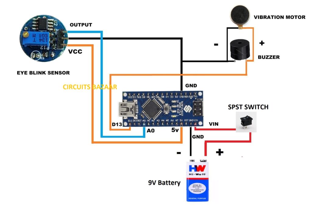
Circuit Diagram of Anti-Sleep Alarm Project:

Proteus Simulation of Anti Sleep Alarm Project Using Eye Blink Sensor.
Here in this simulation, we have used the Arduino library and IR sensor Library. if your proteus version is not having these libraries then you can download them from the internet. To know how to install a new library is given on my youtube channel. below is the video link.
Click Here to download the Proteus simulation file.
Code of the project:
// @circuitsbazaar / Innovative Indian Projects
#define SENSE A0 // IR Sensor

void setup()
{
pinMode(SENSE, INPUT); // Attach the Eye Blink Sensor signal pin
pinMode(LED_BUILTIN, OUTPUT); // 13+ // Buzzer Attached
}
void loop()
{
if(digitalRead(SENSE))
{
 digitalWrite(LED_BUILTIN, LOW);

}
else
{
  delay (2000);
  if(digitalRead(SENSE))
  {
 digitalWrite(LED_BUILTIN, LOW);

}
  else
  digitalWrite(LED_BUILTIN, HIGH);

  }
}
You can buy an eye blink sensor from here
To Buy the Project you can call on +91-8684884488

