Learning Resources & Tutorials
Everything you need to know about Eye Blink Sensor
Table of Content:
What is Eye Blink Sensor
Video Demonstration
Working Principle of Eye Blink Senor
Assembly of the sensor in the goggles
Circuit Diagram to Test the Sensor
Specification
Applications of eye blink sensor
Introduction
Here in this tutorial, we will learn everything about Eye Blink Sensor. This sensor is a boon for drivers driving especially in the nighttime. The application of this sensor is huge in today’s era which we are going to discuss at the end of this tutorial.
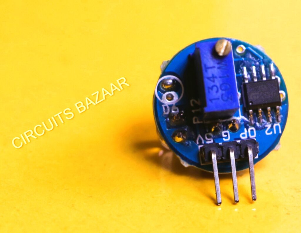
The sensor has three pins as shown below :
Three pins GND (ground), 5V, OP (output)


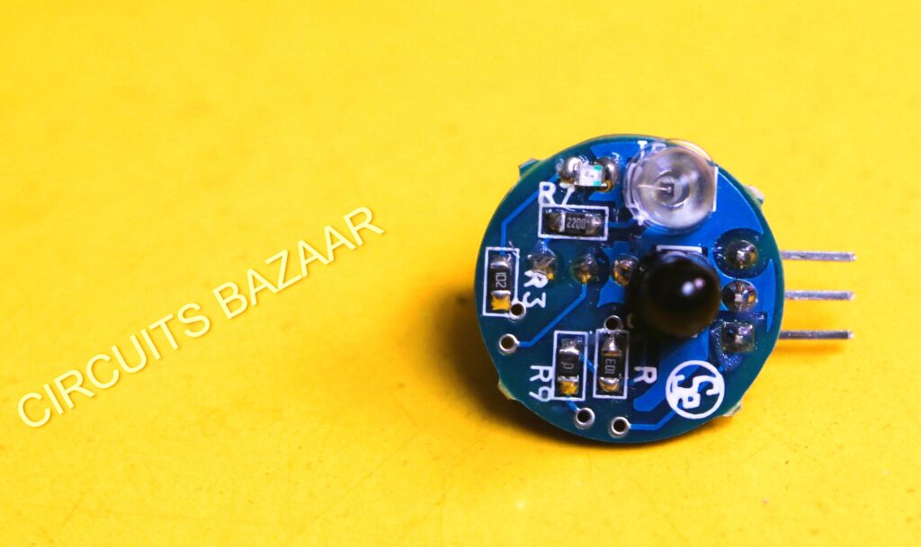
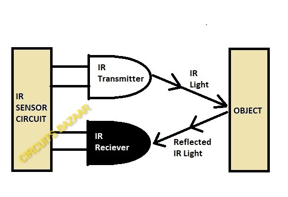
The main component of the Eye Blink Sensor is the infrared sensor. The infrared sensor contains two parts. An IR transmitter and an IR receiver. The IR transmitter emits infrared waves onto the eye. While the receiver continuously searches for variations in the reflected waves which indicates that the eye has blinked or not. If the eye is closed then reflected waves will be received by the IR Receiver and the output of the sensor would be low. If the eye is open then all the IR rays will be absorbed by the eye and the output of the eye blink sensor would be high.
Eyeblink Sensor can be used in a variety of applications including robotics and mechatronics projects as it provides excellent results and is very economic to buy.
Eye Blink Sensor is compatible with Arduino, Raspberry Pi, AVR, PIC and almost all other microcontrollers. The IR Variation Across the eye will vary as per eye blink. If the eye is closed output is low otherwise the output is high.
Video Demonstration:
Working Principle of Eye Blink Senor:

An infrared sensor includes two parts, the emitter (transmitter) & the receiver (receiver), so this is jointly called an optocoupler or a photo-coupler. Here, IR LED is used as a transmitter whereas the IR photodiode is used as a receiver for reflected IR radiations.
The photodiode we are using here in the eye blink sensor is very sensitive to the infrared light generated through an infrared LED adjacent to the photodiode. The resistance of photodiode & output voltage can be changed in proportion to the infrared light obtained. This is the fundamental IR sensor working principle for the eye blink sensor. The comparator IC we are using here on the eye blink sensor board is LM358. This IC will compare the signal coming from the photodiode or IR receiver and the potentiometer on the board. The range of the eye blink sensor you can set by rotating the blue colour potentiometer on the board.
There are two types of IR sensors, active and passive. Passive IR sensors have only the IR receiver, not the Transmitter. But active have both transmitter and receiver. Here we are using an active IR sensor.
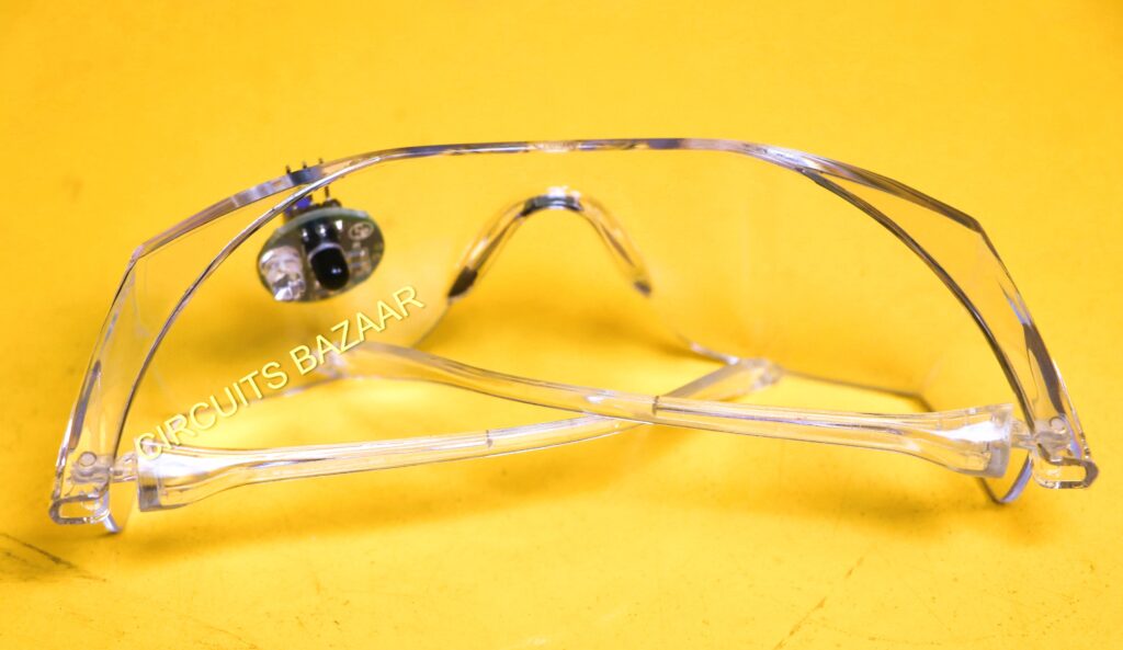
Assembly of the sensor in the goggles:


Circuit Diagram to Test the Sensor:
we have explained the working of the Eye Blink sensor using the simple circuit diagram given below.

Specification:
- Three pins GND (ground), 5V, OP (output)
- EYE BLINK Sensing indication by a red LED
- Instant output digital signal for directly Connecting to the microcontroller
- Compact Size
- Working Voltage +5V DC
- TTL output 5V or 0V
Applications of eye blink sensor:
- Can be used for counting the Eye Blinking frequency of a person.
- Can be used for avoiding fatal accidents on the road because of sleep.
- Can be used to check the state of the patient whether he is awake/conscious or asleep.
- Can be interfaced with any of the microcontroller devices.
Now it’s time to get started with the eye blink sensor. You can buy it from here.

