Electronics Engineering Project Blogs
10 Candidates Quiz Buzzer System Using 8051 Microcontroller
Introduction
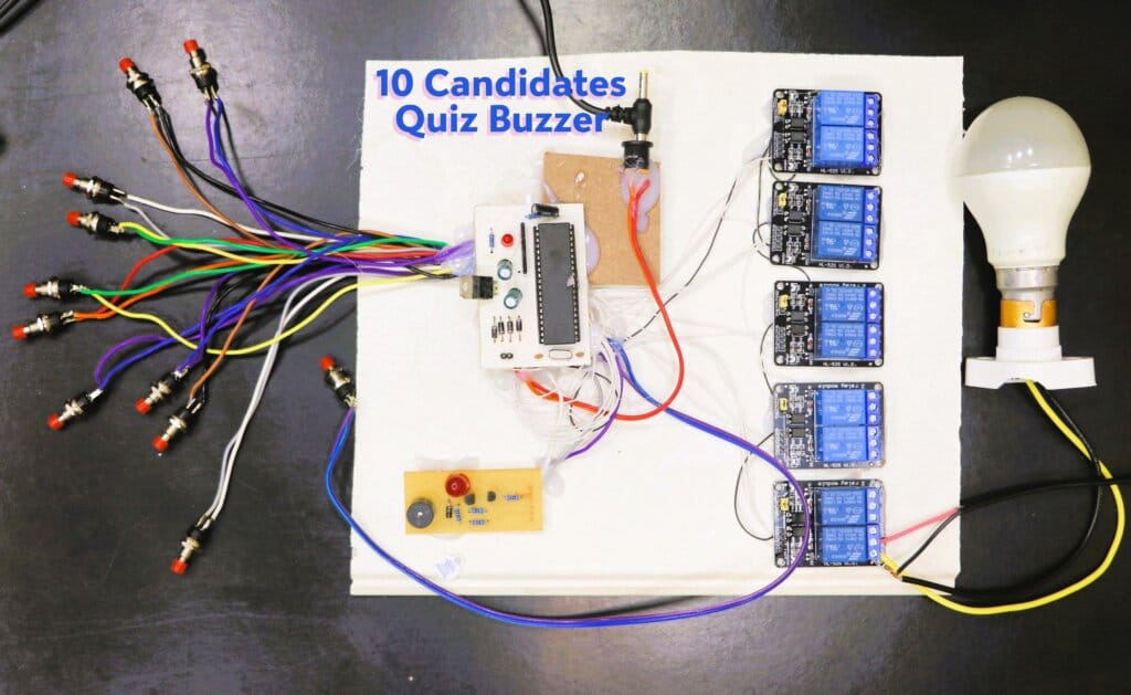
The 10 Candidates Quiz Buzzer System is an innovative project designed for quiz competitions, providing a fair and efficient way to identify the first respondent. Utilizing an 8051 microcontroller, this system connects 10 push buttons, each assigned to a candidate, with corresponding relays controlling high-voltage bulbs (230V). Additionally, a buzzer and an indicator light ensure that the system effectively notifies when a button is pressed. This blog will guide you through the details of this project, from its components and working principle to its applications and future scope.
Components Used
- 8051 Microcontroller: The core processing unit for the system.
- Push Buttons (10): Each button is linked to a candidate.
- Relays (10): Dual relay modules are used to handle high-voltage bulbs.
- Bulbs (10): Indicators that illuminate upon pressing the buttons.
- Buzzer: Provides an audible alert.
- Red Indicator Light: Highlights the active buzzer state.
- Reset Button: Resets the system for the next quiz round.
- Power Supply Unit: Supplies power to the microcontroller and peripherals.
- Connecting Wires: Establish the circuit connections.
- Breadboard/PCB: For assembling the components.
Working Principle
The system operates as follows:
- Initial State: The relays remain deactivated, bulbs are off, and the buzzer is silent.
- Button Press: When a candidate presses their push button:
- The corresponding relay activates.
- The associated bulb lights up.
- The buzzer starts beeping, and the red indicator light turns on.
- Reset: The buzzer and light remain active until the controller presses the reset button. Once reset, the system returns to its initial state, ready for the next round.
The microcontroller monitors all inputs (push buttons) continuously. Using a simple polling algorithm, it ensures only the first button press is registered, avoiding conflicts.
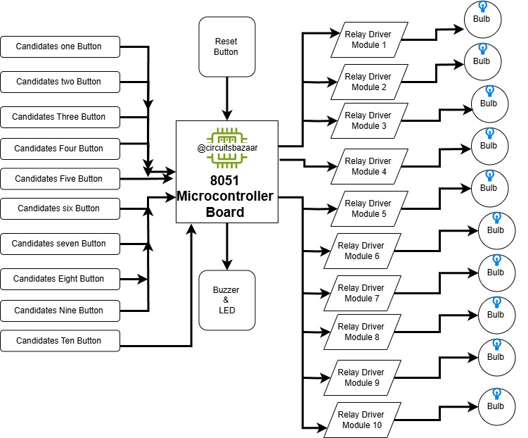
Block Diagram

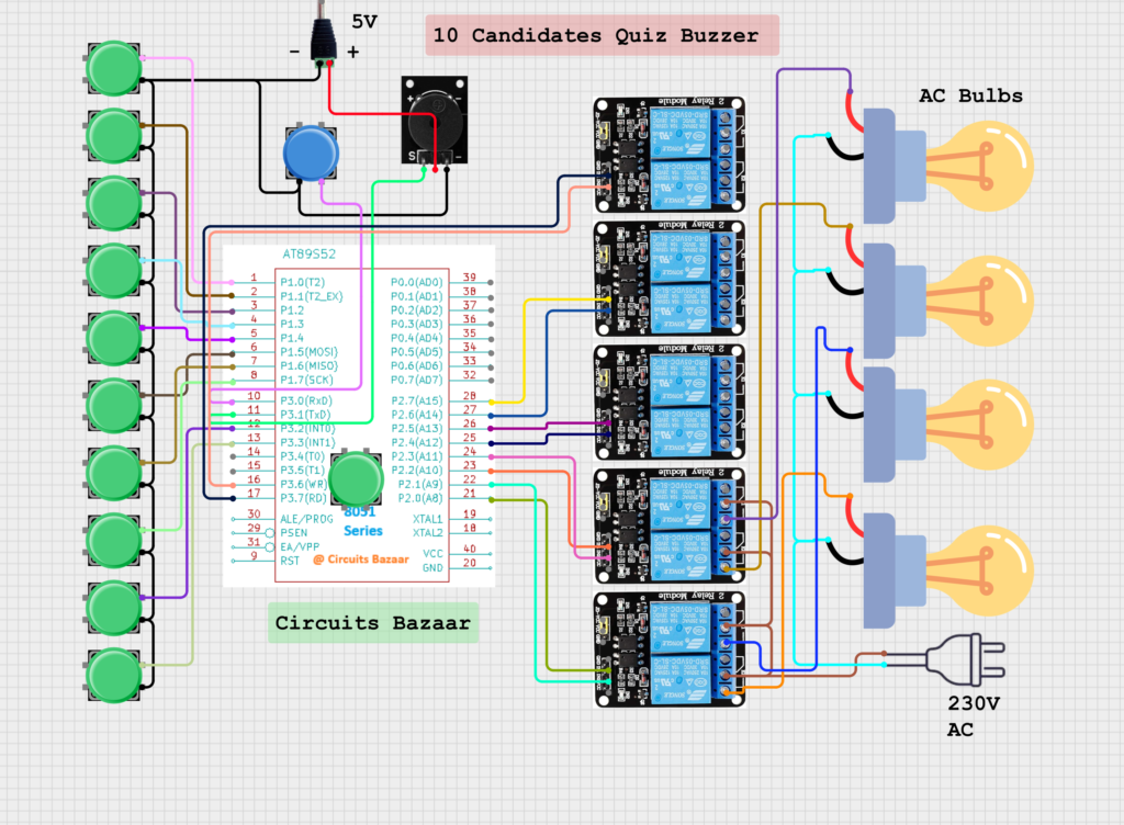
Circuit Diagram

Video Demonstration
Code Implementation
Here is the code for the project:
#include <reg51.h>

#define dataport P0
#define key P3

sbit in1 = P1^0;
sbit in2 = P1^1;
sbit in3 = P1^2;
sbit in4 = P1^3;
sbit in5 = P1^4;
sbit in6 = P1^5;
sbit in7 = P1^6;
sbit in8 = P1^7;

sbit reset = P3^0;
sbit buz = P3^1;

sbit in9 = P3^2;
sbit in10 = P3^4;

sbit rl1 = P2^0;
sbit rl2 = P2^1;
sbit rl3 = P2^2;
sbit rl4 = P2^3;
sbit rl5 = P2^4;
sbit rl6 = P2^5;
sbit rl7 = P2^6;
sbit rl8 = P2^7;

sbit rl9 = P3^6;
sbit rl10 = P3^7;

void delay(unsigned int msec)
{
    int i, j;
    for (i = 0; i < msec; i++)
        for (j = 0; j < 1275; j++);
}

void main()
{
    rl1 = rl2 = rl3 = rl4 = rl5 = rl6 = rl7 = rl8 = rl9 = rl10 = 0;
    delay(150);
    rl1 = rl2 = rl3 = rl4 = rl5 = rl6 = rl7 = rl8 = rl9 = rl10 = 1;
    delay(50);

    buz = 1;

    while (1)
    {
        if (in1 == 0)
        {
            delay(10);
            if (in1 == 0)
            {
                rl1 = 0;
                buz = 0;
                while (reset == 1);
                buz = 1;
                rl1 = 1;
            }
        }
        // Similarly, handle in2 to in10.
    }
}
Applications
- Quiz Competitions: Ensures fairness by registering only the first respondent.
- Game Shows: Used in buzzer rounds to identify participants.
- Educational Institutes: For conducting student competitions.
Advantages and Disadvantages
Advantages:
- Simple and cost-effective design.
- Ensures fairness by locking the first input.
- Scalable for more participants by adding additional modules.
Disadvantages:
- Limited to 10 participants in the current setup.
- Relays handling high voltage require safety precautions.
Challenges in Completing the Project
- Component Compatibility: Ensuring all components, especially relays and the microcontroller, are compatible with each other.
- High-Voltage Safety: Handling 230V AC safely while working with the bulbs and relays required extra precautions.
- Debouncing Push Buttons: Mechanical switches often cause noise or multiple signals; implementing a delay to debounce the buttons was necessary.
- Circuit Complexity: Managing multiple connections on a single PCB or breadboard without errors required precise planning.
- Power Supply Stability: Ensuring a stable and noise-free power supply to avoid malfunctions.
- Debugging: Identifying and fixing errors in the code and hardware connections during testing phases.
Future Scope
- Wireless Integration: Replace wired buttons with wireless modules like RF or Bluetooth.
- LCD Display: Add a display to show the winner’s name or seat number.
- Voice Alerts: Incorporate audio feedback to announce the winner.
- IoT Connectivity: Enable remote monitoring and control via a smartphone app.
Conclusion
The 10 Candidates Quiz Buzzer System is an ideal project for educational and entertainment purposes. Its simple design, efficient functionality, and potential for scalability make it an excellent choice for quiz competitions. By following this guide, you can replicate or modify the system to suit your specific requirements.
Stay tuned for more innovative projects!

